| docs | ||
| schematics | ||
| .gitignore | ||
| c3lingo-mixer.pdf | ||
| LICENSE | ||
| README.md | ||
| vu_meter.pdf | ||
Conference Interpreter Unit
c3lingo.org is doing the great job of translating many talks of the Chaos Communication Congress and other CCC-related events to multiple languages. But the required hardware for simultaneous translation is quite expensive to rent, even if it's "just" a specialized analog audio mixer.
So the idea was born to design an easy to use hardware with the special requirements of our interpreters in mind.
Requirements
The hardware unit should deliver the native audio (stage/ hall mix) to the interpreter's headset and provide a sum of all interpreter's microphone to the input of the video streaming/ recording chain. Mixing of the final translated audio (ducking the native audio with the translation) will be done as part of the streaming/ recording chain, so the interpreter unit should just provide the sum of all microphones.
Normally just 2 interpreters will provide one translation, but demanding talks might require 3 people. So either 3 headphone inputs/ outputs should be provided or it must be possible to daisy-chain multiple units.
The user interface of the unit should be as simple, as possible to decrease the risk of mis-configuration. This means, that no compressor and equalizer will be added in the input group.
General requirements:
- Line input of stage/ hall mix (native language) (XLR/ 6.3 mm balanced jack combo connector)
- 3x Microphone input (XLR) (at first just dynamic microphones)
- VU-Meter for each input channel. (Perhaps with special color scheme: too quiet, good, too loud, clipping)
- Fader/ Potentiometer for gain control
- On-Air switch (on/ off position, with state LED)
- Temporary mute button (momentary switch)
- 3x Headphone output (6.3 mm mono/ stereo (2x mono) jack)
- Should output mix of native audio, own microphone and other translator's microphone
- Potentiometer for output volume
- Potentiometer for volume of own microphone in the mix
- Potentiometer for volume of other two microphones in the mix
- Outputs:
- Sum of all translators (XLR/ 6.3 mm balanced jack combo connector)
All inputs (besides the microphones) and outputs should:
- expect/ deliver a nominal level of +6dBu (german TV broadcast standard, 0 dBu = 0,775 Veff)
- be transformer balanced and galvanically isolated
This results in a signal flow like this: 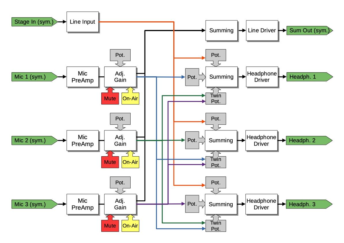
Status
Tasks
- Requirements collection
- Electrical design draft/ proof of concept (breadboard)
- Proof of concept validation
- First PCB layout
- More testing/ validation
Help is always appreciated!
Implemented Requirements
- Microphone input
- Line input
- Microphone summing and line output driver
- Adjustable headphone mix and output volume
- ESD protection and galvanic isolation of line inputs and outputs
- VU meter (own PCB)
- Mute and On-Air buttons
Electrical Design
This chapter contains some notes on the electrical design. Currently just the sources of the used circuit designs.
Sources and Design Considerations
Microphone Input
Preamplifier
For the microphone preamp, we are using the NE5534 low-noise opamp with a circuit design from circuitlib microphone pre-amp.
Controllable Amplification
In a normal mixer, you would be able to lower the microphone's volume to zero. But in our case we just need on/ off and some gain range to adjust for different microphones and loudness of different people.
TODO: Integrate the On-Air button with it's LEDs
Line Input/ Input Module
The line input must not be amplified at all, because loudness control of the headphones is done by the headphone amplifier section. But the differential line-level signal must be converted to a single-ended signal by the input stage.
The current design uses a LM833N opamp to convert the balanced signal into a single ended signal and has a second LM833N to provide some degree (+- 6 dB) of "factory" adjustment. The second part of that circuit was taken from the circuitlib audio mixer tutorial.
TODO: How to achieve galvanic isolation?
Summing
Summing is needed in two places: Creating the sum of all microphones (not adjustable, fixed output gain) and for the headphone mix (one input level adjustable). A simple summing circuit using one operational amplifier is enough for our application, like in circuitlib audio mixer tutorial.
The mixer design uses inverting op-amp circuits, because they require less components and signal routing. Normally an audio mixer should take care of adding signals in-phase, because otherwise two microphones might cancel each other out. In our case, there are just two types of summing: All microphones for the interpreter unit's line-out and the individual headphone mixes. Because the stage input is quite independent of the interpreter's microphones, no special phase/ inversion considerations are needed. And the microphones connected to our unit will experience the same inversions anyways.
Line Output Driver
Line Output conversion is done by the DRV134 IC.
TODO: How to achieve galvanic isolation?
Headphone Output Driver
The headphone output needs a maximum output power of about 0.1 W and should put the mono signal on both stereo channels of the TRS jack.
For the first draft, we're using one LM386 audio power amplifier even though it has a quite high minimal amplification of factor 20.
VU Meter
When searching for VU meter circuits, many use the LM3916 LED bar graph driver, which already has the right scaling built in. But this chip is obsolete and not produced any more, so we designed our own chain of comperators to drive a set of LEDs.
User Interface Hardware
For the potentiometers, we first wanted to use ones with a conductive plastic resistor element for maximum longevity from Bourns, but these are hard to find with logarithmic scaling. An affordable and easily obtainable (Reichelt) alternative was found in the Alps RK11K and RK14K series. They are available in linear and logarithmic scale, as well as single (mono) and dual (stereo) units and have a nice feeling.
Another potentiometer from Omeg was tried, but it had a "jump" in the resistor value at some knob positions.
TODO: On-Air button
Notes
A dynamic microphone needs at least 50-60 dB gain in the pre-amp, because a typical signal is at about 1 - 100 uV (-118 to -78 dBu or -120 to -80 dBV).
Line level in professional audio gear is at +4 dBu, which is 1.228 V (RMS). Because 0 dBu is defined as 1 mW at a load of 600 Ohm, which needs a voltage of 0.77 V. Increasing the voltage by a factor of 10 is an amplification of 20 dB.
BoM
Approximate prices in Euro.
Connectors and Buttons (User Interface)
| Count | Art. No. | Description | Price |
|---|---|---|---|
| 1 | Neutrik NAC3 MPA-1 | Main Power Input | 3,33 |
| 1 | Neutrik NCJ 6 FAH | Line Input | 1,27 |
| 1 | Neutrik NC3 MD-LX | Line Output | 3,22 |
| 1 | TODO |
| 3x1 | Neutrik NC3 FD-LX | Microphone Input | 3,44 | | 3x1 | Neutrik NJ3 FP-6-C | Headphone Output | 5,40 | | 3x1 | TODO | Mute Button | TODO | | 3x1 | TODO | On-Air Button | TODO | | 3x4 | Alps RK11K1120-A503 | 50K log. Gain/ Vol. | 1,32 | | 3x1 | Alps RK14K12B0A0R | 50K log. Vol. (st.) | 1,50 | | 1 | Vishay M64{Y,Z}104 | 100K Trim Pot. | 0,95 |
Sub-Components
| Count | Art. No. | Description | Price |
|---|---|---|---|
| 1 | Traco Power TXL 035-1515D or TOP 60533 | Power Supply | ~48,00 |
PCB Components: TODO when schematic is finished
| Count | Art. No. | Description | Price |
|---|---|---|---|
| 3 | NE5534 | Low-noise Op-Amp | 0,54 |
| 8 | LM833 | Generic Op-Amp | 0,88 |
| 3 | LM386N-4 | Audio Power Amp | 0,83 |
| 1 | DRV143 | Line Driver | 4,50 |
| TODO | TODO | El. Capacitor | TODO |
| TODO | TODO | Cer. Capacitor | TODO |
| TODO | TODO | Resistor | TODO |
VU Meter Components
| Count | Art. No. | Description | Price |
|---|---|---|---|
| 1 | Vishay M64{Y,Z}104 | 50K Trim Pot. | 0,95 |
| 1 | LM833 | Generic Op-Amp | 0,88 |
| 2 | 1N4148 | Signal Diode | 0,02 |
| 1 | 1k Metal Film | Resistor | TODO |
| 1 | 3.9k Metal Film | Resistor | TODO |
| 1 | 47 uF | El. Capacitor | TODO |
| 1 | 100k Metal Film | Resistor | TODO |
| 3 | LM339 | Quad-Ch. Comperator | 0,29 |
| 5 | 100 nF | Cer. Capacitor | TODO |
| 1 | 1 uF | El. Capacitor | TODO |
| 5 | Vishay TLHR 5404 | LED red | 0,18 |
| 4 | Vishay TLHY 5404 | LED yellow | 0,14 |
| 3 | Vishay TLHG 5404 | LED green | 0,17 |
| 12 | 390R | Resistor | TODO |
| 1 | 39R | Resistor | TODO |
| 2 | 68R | Resistor | TODO |
| 1 | 100R | Resistor | TODO |
| 1 | 150R | Resistor | TODO |
| 1 | 270R | Resistor | TODO |
| 1 | 390R | Resistor | TODO |
| 1 | 680R | Resistor | TODO |
| 1 | 1K | Resistor | TODO |
| 1 | 1.5K | Resistor | TODO |
| 2 | 2.7K | Resistor | TODO |
| 1 | 3.9K | Resistor | TODO |